AirPower’s proposed technology combines a closed CO₂ power-cycle arrangement with an open atmospheric-air cycle. The design uses air compression, heat storage, controlled expansion, and staged compressed-air delivery to pursue several useful outputs within one integrated system.
The disclosed design includes opposed piston assemblies, heat-storing recuperators, and compressed-air accumulators.
The proposed machine uses two opposed CO₂ assemblies operating half a cycle apart. One side is heated while the other is cooled. The resulting difference is intended to move the common shaft and drive the compression of atmospheric air.
Atmospheric air enters the machine and passes through compression, heat-management, storage, and expansion stages. The design seeks to use the processed air for electricity generation, mechanical work, heating, cooling, ventilation, and moisture recovery.
Two assemblies alternate between heating and cooling as part of the proposed operating sequence.
A mirrored arrangement mechanically connects the two sides of the machine.
Molten-salt phase-change recuperators are intended to capture heat from compression and preheat incoming air.
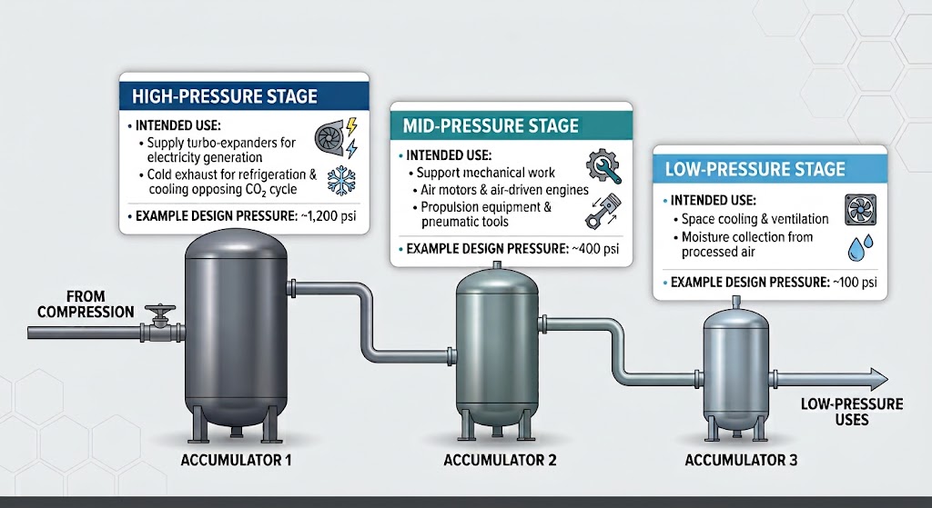
A cascade of pressure levels is intended to distribute compressed air across different output applications.
Expansion equipment is intended to produce useful work and electricity while creating a cold exhaust stream.
Rack-and-pinion hydraulic brakes hold the common shaft during the staged release of compressed air.
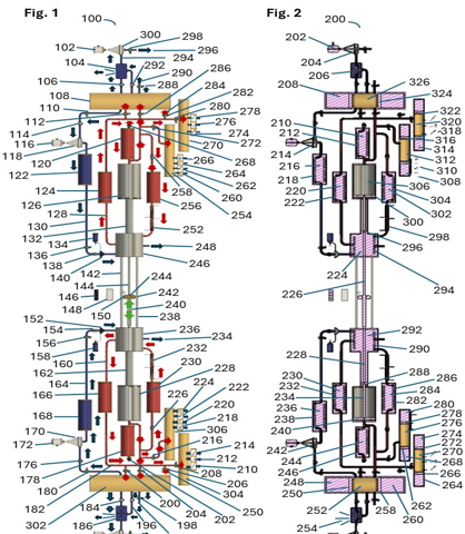
The two sides of the proposed machine follow the same sequence half a cycle apart. While one side compresses air, the other is being cooled and prepared for the next stroke.
Electric heating charges the molten-salt recuperators on one side, while nitrogen cools the CO₂ on the opposing side. This establishes the initial heating and cooling conditions described in the design.
The returning piston draws atmospheric air through a recuperator. Stored heat preheats the incoming air before it fills the cylinder.
Heated CO₂ drives the piston to compress the air. The design circulates hot compressed air through coils associated with the CO₂ reservoir as part of its heat-feedback arrangement.
At the top of the stroke, rack-and-pinion hydraulic brakes hold the common shaft while compressed air is released.
Compressed air is released into accumulators at different pressure levels. These stages are intended to supply electricity-generation equipment, mechanical applications, cooling, and ventilation.
Cold turbo-expander exhaust is intended to cool one CO₂ assembly while stored heat warms the other. The shaft reverses and the sequence repeats.
The presentation describes a cascade of accumulators, with different pressure levels assigned to different uses. The following values are examples from the proposed design, not published equipment ratings.
Intended to supply turbo-expanders for electricity generation, with cold exhaust used for refrigeration and cooling the opposing CO₂ cycle.
Intended to support mechanical work through air motors, air-driven engines, propulsion equipment, and pneumatic tools.
Intended to support space cooling, ventilation, and moisture collection from the processed air.
Intended use of heat formed during air compression.
Intended use of the temperature reduction associated with compressed-air expansion.
Collection of moisture condensed from atmospheric air.
Proposed applications using direct compressed-air drive or electric drive.
AirPower identifies potential applications in off-grid communities, disaster relief, agriculture and aquaculture, cold storage, industrial facilities, water-scarce regions, and data centers. The presentation also explores direct compressed-air propulsion and electric-drive applications for vehicles, vessels, aircraft, and the GravityPlane concept.
The September 2026 executive summary includes calculations, reported tank readings, extrapolations, and design objectives. These have different evidentiary status and should not be interpreted as measured performance of the proposed engine.
588°F | A calculation for air initially at 80°F and compressed from 14.7 to 150 psi. Not an operating-prototype measurement. |
1,998°F | A calculation for air preheated to 500°F and compressed to 395 psi. Not a measured engine operating temperature. |
3,639 psi at 220°F | Tank readings attributed in the presentation to an industrial-gas supplier. The underlying measurement record is not supplied separately in the presentation. |
Approximately 2,600 psi | A calculated net compression-pressure figure described for the heated and cooled CO₂ arrangement. Not a verified machine output rating. |
Approximately 15,000 psi at 500°F | An extrapolation identified in the presentation as unverified. |
91.1% | A theoretical Carnot-limit example, not measured engine efficiency. |
Approximately 140 kW | A theoretical pneumatic-power calculation, before real-world losses. Not demonstrated net electrical output. |
Up to one week | A heat-or-cold storage claim for insulated phase-change recuperators, not an operating-prototype test result. |
AirPower’s September 2026 executive summary identifies the following patent application for its proposed ambient-air heat-energy technology.
Title of invention | Heat Energy from Ambient Air Harnessing |
U.S. application number | 19/755,207 |
Filing date | July 27, 2026 |
Inventor | Robert D. Hunt, Sr. |
Invention date identified | July 11, 2025 |
Assignee identified | AirPower, LLC |
Status reported in September 2026 | Patent pending |
Patent counsel identified | Thomas St. Paul Keaty, II, Keaty Law Firm |
The application describes the proposed dual-cycle apparatus, heat-storing recuperators, compressed-air accumulator cascade, and operating sequence. The presentation identifies twelve drawing sheets associated with the application.
The presentation describes a cascade of accumulators, with different pressure levels assigned to different uses. The following values are examples from the proposed design, not published equipment ratings.
Develop a high-pressure test stand to investigate the CO₂ temperature-and-pressure behavior described in the proposed design.
Construct and instrument the opposed dual-cycle machine to evaluate its operating sequence and the objective of sustained operation after start-up.
Work with development partners, licensees, and investors to support further engineering and investigate potential pilot applications.
AirPower is seeking organizations with the technical expertise, development capabilities, and resources to help evaluate and advance the proposed system.